Pierrerue tutorial : Différence entre versions
(→4. Orthorectification) |
|||
| Ligne 75 : | Ligne 75 : | ||
<pre>mm3d Pims2MNT MicMac DoOrtho=1 Repere=Repere-Facade1.xml Pat="facade1.*JPG"</pre> | <pre>mm3d Pims2MNT MicMac DoOrtho=1 Repere=Repere-Facade1.xml Pat="facade1.*JPG"</pre> | ||
The correlation map resulting, calculated into the facade n°1, can be found into the folder ''PIMs-TmpBasc'' with the name ''PIMs-Merged_Correl.tif''. This file contains the correlation results : white is corresponding to a very good correlation scores ; more the grey is dark, less the matching process went well. | The correlation map resulting, calculated into the facade n°1, can be found into the folder ''PIMs-TmpBasc'' with the name ''PIMs-Merged_Correl.tif''. This file contains the correlation results : white is corresponding to a very good correlation scores ; more the grey is dark, less the matching process went well. | ||
| + | <br> | ||
| + | Once the depth map processed, MicMac compute into the PIMs-ORTHO repertory the orthoimages for each image, aswell as incidence pictures, with the angle between the facade and the perspective ray (images Incid_facade1DSC###.tif) and images with hidden parts, that show in white the hidden parts into the image (imgaes PC_facade1DSC###.tif). | ||
| + | <br> | ||
| + | After the calculation, each orthoimages should be mosaiced. The choice of the image to use for each pixel is done with these specificity : no hidden parts, best angle of attack, continuity in the choice of images : <pre>mm3d Tawny PIM's-ORTHO/</pre> | ||
| + | The result is an image created into ''PIMs-ORTHO'' folder, called Orthophotomosaic.tif. Metadatas associated are available into the file Orthophotomosaic.tfw. We can see the resolution chosen for the orthoimage computation here (1.1mm). | ||
| + | |||
| + | |||
Version du 1 mars 2016 à 13:26
Sommaire
Download
- There is a direct download link to download this dataset at :
http://micmac.ensg.eu/data/pierrerue_dataset.zip
Once you have download it, you have to UnZip the ".zip" archive.
Description
- 31 JPG images
- 1 file containing the support points (Pierrerue.xml)
- We will use the folder 001_Elements-de-georeferencement
About the data
The shooting contain 31 images, taken with the Sony alpha850 with a 244mm lens. Check that the folder contains images recovering :
- facade n°1
- facade n°2
- the corner between these 2 façade (images link).
Support points are available and allows to georeference the readings (see the folder 001_Elements-de-georeferencement).
Tutorial
1. Set up the images
All the images should be set up simultaneously, in order that the georeference process will be expressed into one only cordinate system. First, we can run the tie-points search :mm3d Tapioca MulScale ".*JPG" 600 2000
Then, we have to define the settings of the camera used from the images covering the corner between the 2 facades (more suitable than the others, because of the depth).
mm3d Tapas RadialStd "angle.*JPG" Out=Calib24mm
Into the command prompt, we can check if the residual from the images is admissible (around the half pixel). We can check also the number of connection points, aswell as the percentage of points keeped ("99.8258 of 28466" : 99.8% of the connection points keeped from 38466 points calculated).
We can process yet the setting up of all the images. starting from the camera we calculated before.
mm3d Tapas RadialStd ".*JPG" InCal=Calib24mm Out=MEP
Into the command prompt, we can control residual during the process. At the last step, we can see that the image residual are, for all the images, less than a half-pixel. We control also the number of support points, aswell that the percentage of points keeped ("99.8258 of 38466" : 99.8% of the support points keeped from the 38466 points calculated).
The AperiCloud command alllows to generate 3D clouds, containing all the support points obtained with Tapioca, and the position of the cameras obtained from the Tapas output.
mm3d AperiCloud ".*JPG" Pierrerue
The result of this command can be seen for example with the meshlab software.
2. Set up the images into the coordinates system of the support points
Now we have to measure the support points available to georeference the images, and so the incoming products, into the reference coordinate system.
Explaining the process :
- 1. We measure 3 support points well distributed (SaisieAppuisInit command) ;
- 2. We can now create a 3D similarity (transformation from 7 settings containing one scale coefficient, one translation into space and one space rotation) between the arbitary system calculated while the setting up and the coordinate system chosen (GCPBascule command) ;
- 3. We have now to measure the remaining points : the absolute orientation calculated from the previous step, allows to suggest an approximated position for each points (SaisieAppuisPredic command) ;
- 4. We affine the absolute orientation (GCPBascule command) ;
- 5. We start the final computation for the setting up (this offset allows to find the best position/orientation of the cameras while using the points measurements on the linking points and on the support points) ; (Campari command).
- 1. Measurements of almost 3 support points on the facade n°1 (At least one point should be measured to be valid on at least two images). To set the points, you need to get to know the the position of the 3 points thanks to the folder 001_Elements-de-georeferencement.
mm3d SaisieAppuisInitQT "facade1DSC0589[8|9].JPG" Pierrerue 1001 MesureFacade.xml
mm3d SaisieAppuisInitQT "facade1DSC0588[3|5].JPG" Pierrerue 1002 MesureFacade.xml
mm3d SaisieAppuisInitQT "facade1DSC0589[3|6].JPG" Pierrerue 1121 MesureFacade.xml
- 2. Computation of the 3D similarity (absolute orientation)
mm3d GCPBascule ".*JPG" MEP MEP-Basc Pierrerue.xml MesureFacade-S2D.xml
- 3. Measurement of all available points :
mm3d SaisieAppuisPredicQT "facade.*JPG" MEP-Basc Pierrerue.xml MesureFacade-Final.xml
We must now validate the points left.
- 4. Update computation of the absolute orientation.
This time, we need all the support points to calclulate the 3D similarity of the absolute orientation.
mm3d GCPBascule ".*JPG" MEP-Basc MEP-Basc2 Pierrerue.xml MesureFacade-Final-S2D.xml
- 5. Final adjustement
mm3d Campari ".*JPG" MEP-Basc2 MEP-Terrain GCP=[Pierrerue.xml,0.02,MesureFacade-Final-S2D.xml,0.5]
This computation adjustement use to find the best position/orientation of the cameras when the shooting was made assuming that the support points have a 0.02m accuracy, and the linking points have a 0.5 pixel accuracy. This values allows to ponderate the measurements.
It suits, at the end of the process, to control the residues on the support points and on the images residuals.
The residual images look like this :
| | RESIDU LIAISON MOYENS = 0.547721 pour Id_Pastis_Hom Evol, Moy=2.38308e-07 ,Max=0.00295916
3. 3D Reconstruction
As we did for the Fountain exercise, we have to do the 3D reconstruction with the image geometry with the C3DC tools. First, we have to limit the reconstruction area. To process it, we have to create a mask on the cloud points (AperiCloud), that we have to recalculate in the new set up.mm3d AperiCloud ".*JPG" MEP-TerrainTo limit the computation area, we will create a 3D mask :
mm3d SaisieMasqQT AperiCloud_MEP-Terrain.plyOnce the mask is created, we can launch the 3D reconstruction :
mm3d C3DC MicMac "facade.*JPG" MEP-Terrain Masq3D=AperiCloud_MEP-Terrain.ply Out=C3DC_MicMac_Pierrerue.ply
The C3DC_MicMac_Pierrerue.ply file can be open with Meshlab.
4. Orthorectification
To realize orthorectifications of the Pierrerue facade, we have to define a temporary landmark for each facade, where the Z axis will be perpendicular to the facade. In the first time, we will work on facade n°1. We processing it in 2 steps :
mm3d SaisieMasqQT facade1DSC05893.JPG Attr=Facade12. Computation of a local landmark where the Z axis is perpendicular and going through the support points included into the masks :
mm3d RepLocBascule "facade1.*JPG" Ori-MEP-Terrain HOR Repere-Facade1.xml PostPlan=_MasqFacade1
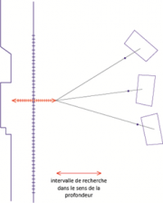
The HOR setting show that for the Ox axis of our orthoimage, we use the horizontal of our worksite. It can be done here, because the set up MEP-Terrain was obtained from support points. The orthoimage will be calculated from new landmark. It is necessary here to reproject the 3D reconstruction process into this new landmark. Normally, a depthmap will be calculated into the orthorectification map : it's about an image applied on the object, where the pixels show the distance from map. We describe it as 2.5D (3D information isn't available only for a finite number of positions).
The Pims2MNT command allows to create a depth map into the map of the facade n°1 (the one calculated before : Repere-Facade1.xml) :
mm3d Pims2MNT MicMac DoOrtho=1 Repere=Repere-Facade1.xml Pat="facade1.*JPG"
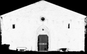
The correlation map resulting, calculated into the facade n°1, can be found into the folder PIMs-TmpBasc with the name PIMs-Merged_Correl.tif. This file contains the correlation results : white is corresponding to a very good correlation scores ; more the grey is dark, less the matching process went well.
Once the depth map processed, MicMac compute into the PIMs-ORTHO repertory the orthoimages for each image, aswell as incidence pictures, with the angle between the facade and the perspective ray (images Incid_facade1DSC###.tif) and images with hidden parts, that show in white the hidden parts into the image (imgaes PC_facade1DSC###.tif).
mm3d Tawny PIM's-ORTHO/
The result is an image created into PIMs-ORTHO folder, called Orthophotomosaic.tif. Metadatas associated are available into the file Orthophotomosaic.tfw. We can see the resolution chosen for the orthoimage computation here (1.1mm).
We will now work invidually for each facade. The linking images won't be used anymore, we used them to put all the images into one coordinate system. Usually, support points should be enough to georeference the images into one coordinate system. Setting up the support points and the linking points is however more reliable.
- Field geometry (called "Ortho" or "UrbanMNE" in MicMac) :
The depth map, like a building facade, can be calculated with field geometry. The depth map resulting from the dense matching is an image fitted on the midplane of the object. Each pixel from the depth map is reprojected into different depths in the images which see it. the similarity between projected points is calculated (correlation coefficient). It's the depth that gave the most relevant points that will be kept.
To work with field geometry, we assumed that the depth is wanted into the Z from coordinate system. In this case, we have to define a temporary landmark for each facade, where the Z axis will be perpendicular to the midplane of the facade. We have to proceed in 2 steps :
- 1. Mask creation into the midplane :
mm3d SaisieMasqQT facade1DSC05893.JPG Attr=Facade1
- 2. Computation of a local landmark where the Z axis is perpendicular to the landmark and going through the linking points contained into the mask.
mm3d RepLocBascule "facade1.*JPG" Ori-MEP-Terrain HOR Repere-Facade1.xml PostPlan=_MasqFacade1
Now we will calculate an image mosaic from the midplane of the facade.
mm3d Tarama "facade1.*JPG" Ori-MEP-Terrain Repere=Repere-Facade1.xml Out=TA-Facade1
This mosaic is useful to define the area we want to work on. The SaisieMasq command is used this time to limit the computation area (like for the previous exercise on the Sigonce fountain).
mm3d SaisieMasqQT TA-Facade1/TA_LeChantier.tif
We can now calculate dense correlation into field geometry :
mm3d Malt Ortho "facade1.*JPG" Ori-MEP-Terrain Repere=Repere-Facade1.xml DirMEC=MEC-Facade1 DirTA=TA-Facade1
The Malt tool will start to process the computation on very sub-sampled images, then increase progressively the image size (while affining the initial result with the previous computation) until sub-sampled images from a factor 2 (default settings in the field geometry computation).
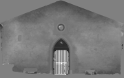
During the process, it is recommended to control if the correlation is working by analysing the files : MEC-Facade1/Correl_STD-MALT_Num_#.tif (each files is corresponding at a step of the image pyramid). These files are containing the correlation scores : white is a very good correlation result ; more the grey is dark, less the connection did well.
When the depth map is calculated, MicMac compute the orthoimage for each images, aswell as the impact images ; informing the impact angle between the facade and the perspective ray (images Incid_facade1DSC###.tif) and the hidden part from the images. We can see in white the hidden parts from the image (images PC_facade1DSC###.tif).
After processing it, orthoimages for image can be mosaiced. The choise of image use for each pixel is done on these standard : no hidden parts, best angle, linearity into the choice of the images.
mm3d Tawny Ortho-MEC-Facade1/
The result is an image created into Ortho-MEC-Facade1 folder, called Ortho-Eg-Test-Redr.tif. Metadatas associated are available into the file MTDOrtho.xml. We can see the resolution chosen for the orthoimage computation here (1.1mm).
4. 3D visualization of the products
From the depth map calculated previously, we can now generate some 3D products, after going in the right folder, from the Malt output :
cd MEC-Facade1/
- Creating a faded relief image :
mm3d GrShade Z_Num8_DeZoom2_STD-MALT.tif ModeOmbre=IgnE Mask= AutoMask_STD-MALT_Num_7.tif
The file Z_Num8_DeZoom2_STD-MALT.tif can be seen in image viewer software. This image allows you to check the quality of the reconstruction, and analyze if there is noise on the build part.
- Creating an image with grey level :
mm3d to8Bits Z_Num8_DeZoom2_STD-MALT.tif Circ=1 Mask=AutoMask_STD-MALT_Num_7.tif
The file Z_Num8_DeZoom2_STD-MALT_8Bits.tif can be seen into an image viewer software.
- Creating a 3D cloud points :
mm3d Nuage2Ply NuageImProf_STD-MALT_Etape_8.xml Attr=../Ortho-MEC-Facade1 Ortho-Eg-Test-Redr.tif RatioAttrCarte=2
The command Nuage2Ply take as an input the depth map, that will be converted into a cloud points. This cloud will be colorized whith the image named into the Attr argument. The pattern RatioAttrCarte=2 is useful to tell that our cloud points is 2 times less resolution that our initial image, because of the default setting ZoomF=2 used in the field geometry in Malt.
The ply file generated (NuageImProf_STD-MALT_Etape_8.ply) created into the MEC-Facade1 can be seen with Meshlab for example.
5. 3D global reconstruction
Everything comming from the facade n°1 can be done now for the facade n°2.
As an input, we get 2 ply files that we can load simultaneously into meshlab, aswell as 2 orthoimages.


