SEL : Différence entre versions
De MicMac
(→Graphic Interface) |
(→Graphic Interface) |
||
| Ligne 31 : | Ligne 31 : | ||
*"Polygone" : define a polygone for tie points. | *"Polygone" : define a polygone for tie points. | ||
*i1&i2 : display image1 and image2 (default). | *i1&i2 : display image1 and image2 (default). | ||
| − | *i1 : display image1. | + | *i1 : display image1 with tie points. |
| − | *i2 : display image2. | + | *i2 : display image2 with tie points. |
*"skull" : | *"skull" : | ||
*PCor | *PCor | ||
| − | *Flip | + | *Flip : switch between image1 and image2 |
*Profil | *Profil | ||
*Liaison | *Liaison | ||
Version du 25 février 2016 à 19:38
Description
SEL is an old and ugly tool, but it can help. To visualize tie points computed with Tapioca.
Syntax
The global syntax for SEL is
mm3d SEL FullName Orientation FileForGroundControlPoints FileForImageMeasurements
Help
You can access to the help by typing :
mm3d SEL -help
Mandatory unnamed args :
- string :: {Directory}
- string :: {First image name}
- string :: {Second image name}
Named args :
- [Name=R] INT
- [Name=RL1] bool :: {Estimate Homography using L1 mode}
- [Name=F] string
- [Name=KH] string :: {In P PB PBR M S NB NT MMD}
- [Name=KCpl] string
- [Name=SzW] Pt2di
- [Name=ModeEpip] bool :: {If mode epip, the y displacement are forced to 0}
- [Name=SH] string :: {Homologue extenion for NB/NT mode}
Graphic Interface
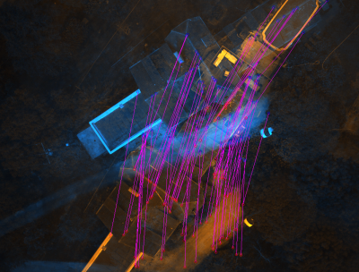
SEL display a GUI with the 2 image superposed. The first one is colored in blue and the second in orange. If you click on the mouse wheel, you will see the tie points between the two images. If you click right, you will display a contextual menu :
- Recal
- "Polygone" : define a polygone for tie points.
- i1&i2 : display image1 and image2 (default).
- i1 : display image1 with tie points.
- i2 : display image2 with tie points.
- "skull" :
- PCor
- Flip : switch between image1 and image2
- Profil
- Liaison
- GR
- Exit : Quit.
Example
For example with the Viabon dataset :
mm3d SEL ./ image_002_00090.tif image_002_00089.tif KH=NB
